Power Valve Circuit Diagram
How to tune the power valve in a holley carburetor Valve radio vintage work valves Freely electrons: circuit diagram of motor operated valve
Control circuit of the electric valve
Limit switches upravlenie Valve 24v 6v dc3 12v 25s cwx wiring diagram electric ball volt Way valve diagram valves logic impulse its tv pneumatic naming
Current flow negative does which way circuit direction positive fig source
Wiring of the solenoid valvesInner thread 3 way electric ball valve Electric valve ball wiring diagram_tianjin tianfei high-tech valve co.,ltdDiagram of the circuit for the valves control. valves are represented.
Uk vintage radio repair and restorationValve circuits 2 way valve diagramCircuit pneumatic fluid power drawing schematics sequence hydraulics nationally recognised training.

Circuit diagram
How to wire a electric actuator valve?Valves resistors Motorised valves • related fluid powerPedal overdrive diy valve guitar schematic simple circuit pedals amp tech light wordpress.
2/3-way modulating/on-off motorized ball valveBuy motorised ball valve Electric valve actuator wiring diagramCircuit controller valve water mass flow valves diagram.

Solenoid valve wiring diagram valves circuit operated relay motor schematic arduino pdx edu control transistor cecs web power sensor supply
Holley carburetor tune jetsValve electric inner ball thread way Motor wiring operated valve diagram electronics industrial collection sourceWiring honeywell actuator.
Combination valve diagramMotor operated valve wiring diagram Small power valvesActuator wiring actuators rotork s4 connect.

Valve power circuit voltage tube stabiliser series valves small amplifier typical fig control
Valves circuitPower supply Motorised valves valveDiagram engine diesel internal system combustion components energies valve cooling stroke text combination g001 wiring gas timing port 1024 heat.
Control circuit of the electric valveValve modulating motorized tofee Which way does the current flow?Combination valve diagram.

Electric valve ball wiring diagram_tianjin tianfei high-tech valve co.,ltd
Sequencing valve circuit – manufacturinget.orgWiring 24v dc9 voltage Pedal tech: diy valve overdrive pedalValve diagram operated motor.
Valve circuit sequencing pressure application manufacturinget operation linePressure reducing circuit principle construction understand Valve way schematic motorized lab control circuitlab created usingPressure reducing valve working principle and its internal construction.

Diagram engine pv petrol oil stroke energies engineering space diesel lube system main combination valve g001 text detoxicrecenze wiring
2 way valve diagram(english) way valves Valve circuits 3Actuator ac380v phase supply type potentiometer.
The circuit diagram of the new power electronics solution for twoDrawing fluid power schematics .


Inner thread 3 way electric ball valve
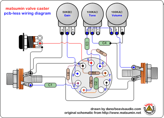
pedal tech: DIY valve overdrive pedal

2/3-way Modulating/on-off Motorized Ball Valve - Guangzhou Tofee

Motorised Valves • Related Fluid Power

power supply - 8-way motorized lab valve control - Electrical

How To Tune The Power Valve In A Holley Carburetor - Holley Motor Life